|
MOLD DESIGN PREVENTS MOLD DAMAGE
FLASH: IT’S RUINING YOUR MOLDS
What are the causes of mold damage?
When a mold is damaged it is usually obvious. It is also usually obvious what has caused
it. Machine malfunction or human error, for example, causes immediate—and
immediately visible—damage to molds. Proper training of personnel, maintenance and
safety programs can avert these dangers.
Another cause of damage is molds being closed on molded parts. In order to prevent this
from causing damage, some sort of molding protection device is built into every molding
machine. A commonly used system closes the mold with very low pressure until the
mold touches, then a limit switch is activated that allows full clamp pressure to be built.
If there is a part left in the mold from the last cycle, the mold will strike it while on low
pressure and will not exert enough force to smash the part—or the mold—the mold will
not close far enough to energize the high-pressure switch. After a certain pre-set time
delay the mold re-opens, probably energizes a no-cycle-warning device and will sit idling
until the problem is corrected and the machine is recycled.
Therefore, during more than 50 years of injection molding, there has been heavy emphasis on perfecting this type of mold protection, and with good reason. However,
despite the efficiency with which these modern systems prevent gross mold damage, the
molder finds that he still has to send out his molds for occasional “maintenance”. Often
this includes re-dressing the parting line and re-machining the cavity and re-polishing the
mold in the parting line area because it has been rolled over. At best, machine production
has to be scheduled around having a particular mold out for repair. At worst, it can mean
interrupting the flow of a customer’s badly needed parts. Yet, molders just seem to
accept this as “normal” and no one has bothered to analyze the reasons for it.
This paper will analyze the cause of damage around the parting line of a mold and will demonstrate that the original cause was flash, how it then feeds on itself and will progressively ruin a mold in which it has taken hold. Then it will show how to prevent this damage and how it is mostly in the design of the mold and not in the heat-treating or hardness of the steel used in the mold.
How does flash cause mold damage?
Before we investigate how flash ruins a mold, let’s look at the steps in a normal molding
cycle, with a mold that is in perfect condition, that is, there is no flash around the parting line:
1. The mold closes.
2. The mold touches, full clamp pressure is developed.
3. Injection takes place and the part is filled.
4. The part is packed out on holding pressure, then cooled.
5. The mold opens and the part is ejected.
6. The cycle is repeated beginning again with step 1.
This process could continue indefinitely and our mold protecting devices as described
earlier will basically prevent all mold damage.
However, let’s go through the cycle one more time. This time the mold will be inadvertently flashed during injection. Injection molders will recognize this as a relatively common problem, whether they mold thermo-plastics or thermosets. Until now, a flashed part was only regarded as being bad because it was a reject part. What does flash do to a mold?
Let’s run through some quick calculations and see. Assume the part being molded is square, ten inches on each side, flat, and that it is .100” thick. (For the sake of simplicity,
we will ignore draft angle and assume that the edges of the part are exactly 90° with
respect to the flat surfaces.) Thus, we are considering a part with a projected area of 100
in.². If it is running in a 300-ton press, the effective clamp pressure is 3 tons/in.². Say the
part is being molded as ABS and that the injection pressure opened the mold by 0.005 in.
and that flash was thus generated around the entire perimeter of the part and was, say,
0.100 in. wide, or an area of 2.01.² (10.1 in.) ² – (10 in.) ² = 102.01 – 100 = 2.01 in.²).
The part, we said, was 0.100 in. thick but since the mold was spread open by the flash an
extra 0.005 in., the molded part immediately following injection will be 0.105 in. thick.
Depending upon the compressibility of the particular resin being used, the part will, in
varying degrees, help keep the mold spread open by 0.005 in. despite the 300 tons of
clamp force. ABS, however, has a linear shrinkage rate of 0.004 to 0.009/in. and thus the
part will shrink (taking the middle figure of 0.0065) to 0.10435 in. thick. The same rate
of shrinkage applies to flash but since it was so small to begin with, the changes in
its dimensions are insignificant. Therefore, even if the molded part originally presented
enough resistance to completely withstand the clamp force of 300 tons, as it now has
shrunk by .00065 in., it will allow the clamp force to exert itself fully on the flash for that
distance. In fact, only about five tons is required to compress the ABS part in question to
the cavity’s dimension of 0.100 in., thereby effectively leaving about 295 tons to exert
itself on the flash for the whole distance. The net result is a pressure of about 295
tons/2.01 in.² or 146 tons/in.² being exerted on the flash which, in turn, will exert the
same pressure on the steel on both sides of it—which is the very edge of the parting line
of the mold. (Exactly how much pressure comes to bear on the steel itself again depends
upon the compressibility of the resin being molded, which we have ignored for
simplicity’s sake. Yet, it is obvious that not ALL of the plastic can be completely
compressed: it must ultimately be pressed into the steel.) The resulting pressure of
248,000#/in.² (146 tons/in.² – 248,000#/in.²) is more than enough to displace even
hardened steel, possibly taking away .0001 inch from the dimension of the parting line.
That 0.0001 inch missing from the parting is not enough to generate flash, but if the process is allowed to continue it very soon will be—and each time this happens it makes
it easier to happen the next time. The flash the first time was .005” thick, the next time
.0051” thick, then .0052”, etc.
Most plastics used in injection molding are far weaker than steel. However, most molders have observed, it is not possible to squeeze it to nothing. Therefore, the steel
moves. How much the steel moves, depends on the hardness and the strength of the steel
verses the hardness and strength of the plastic. You know the old story about two things
can’t occupy the same space. After the mold has flashed many times, the steel will give
to the point where the parts cannot be molded without flash.
How can mold damage due to flash be abolished?
All toolmakers and molders know that molds must be vented. Very few however, realize
the significant importance of venting. Almost no one realizes when a mold is properly
vented it will not be destroyed by flash. By properly venting we mean full parting line
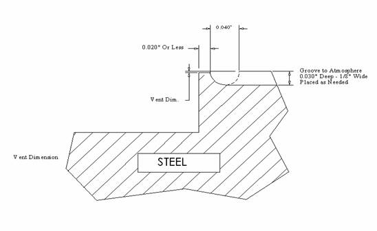
venting. That is, the mold at the parting line does not touch anywhere. The steel is spaced apart by dimension equal to the vent dimension.

Fig I
Now let us go through the flashing example given earlier. This time let’s have the mold
completely vented as in Fig. I. Now we have a half a thousandths clearance between the
steel at the parting line so that when the five-thousandths thick piece of plastic flash is
caught in the mold, it does not have to squeeze it down to the thickness of 0, but only
must be squeezed to half a thousandth. It can do this without damaging the steel. To stop
the damage is that simple and you can prove it by calculating the stress on the steel as the
mold closes back on the flash.

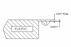
Part Molded with Flash
|

Mold Reclosed On Flash |
Part
Molded with
Flash
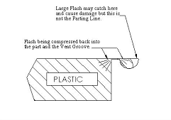
Fig II
|
Mold Reclosed On Flash
Fig III
|
On some molds venting the entire parting line of the mold is expensive. On others it is
very inexpensive. I know that some will argue that it is not necessary to vent a mold all
over the parting line and they are right. No two pieces of steel literally fit together
perfectly so some venting is occurring whether we put vents in or not. However, when
there is an intentional vent around the entire parting line, per Fig. I, the parting
line damage caused by the flash will not occur. You will notice that in the drawings we
have twenty-thousandths land. Theoretically, it should be less then twenty thousandths of
an inch. If we really wanted to develop a parting line that would not overstress, we
would make it closer to being a knife-edge. Then, as the mold closed on the flash, it
would simply cut the flash from the part. Figure II shows the mold opened up .005” and
the plastic molded past the parting line and into the pick-up groove. Figure III shows
what happens as the injection forces that opened the mold disappear and the mold re-closes on the flash. Instead of crushing it, it can move sideward, get squeezed back into
the part, or get squeezed into the groove. It is also better for venting because the less the
land, the better the venting works.
It may be interesting to note that the flash damage usually comes from too large a mold
put in too small a press, thus having the mold flash more often. The second damage is
caused by too small a mold put in too large a press and simply overstressing the steel
with the clamp force. The more steel we have touching, the better and the longer the life
of the mold. I have seen molds where they have vented to atmosphere one half inch wide
and five thousandths deep thus taking away several square inches of contact of the mold.
I have seen molds where the steel has been crushed because of closing with too much
clamp force and yet at the same time they ground in vents that have thrown away many
square inches of steel contact. So keep the vent path to the atmosphere narrow and deep.
Logic Corporation
I have taught this method for many years. A molder in or around the Toronto, Canada
area was re-dressing the parting line on a mold about once a month. He called me many
months later to tell me he did the venting this way and the parting line remained good
after months of molding. Saving a lot.
(I thanked him but did not record his name, if he reads this please call! Thanks)
Paul E. Allen – President
Logic Corporation
80 Turnpike Dr. STE 3
Middlebury, CT 06762
(203) 598-3400
Phone 1-800-325-6442
Fax 203 598-3401
Email: logic@logicseal.com
Comments are welcome.
|
